All Resources
Europa Clipper Scale Model - 3D Print
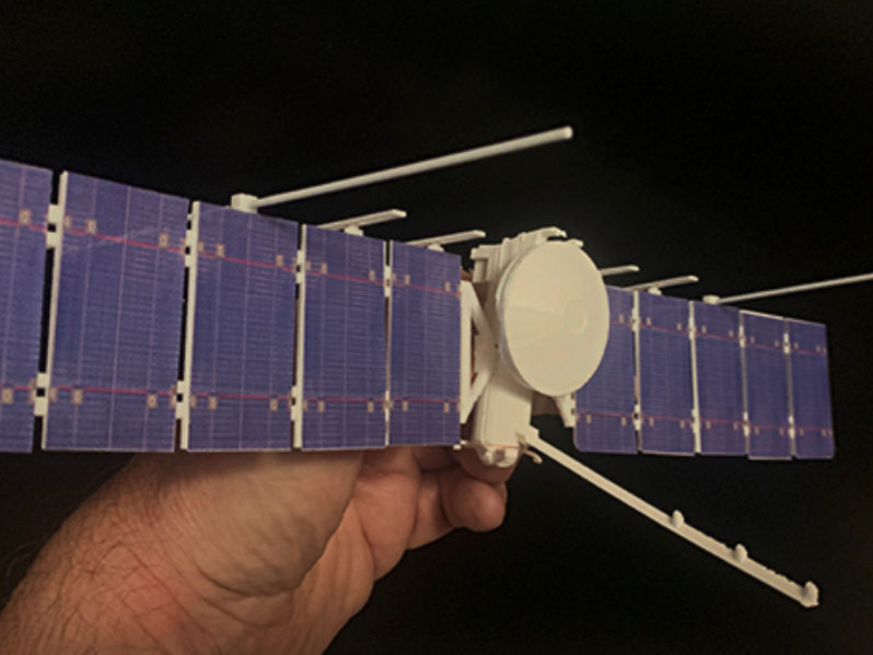
This is a model for anyone who wants to see Europa Clipper's major components and science instruments, and manipulate the solar-array-radar wings.
The spacecraft's X, Y & Z body axes are plainly marked on the model. Attitude Control components shown include Stellar Reference Units, Sun Sensors, Reaction Wheels, and Thrusters. Communications and Gravity Science components include High-Gain Antenna, Medium-Gain Antenna, Low-Gain Antennas, and Fan Beam antennas. To identify the instruments and spacecraft components, use this interactive visualization.
Printing: All the model's components are designed to be simple enough for FDM printing* so you can just carry the .stl files to your nearby desktop 3D printer's software, and use default settings without rafts or support material. Also, there is a single-file whole Body .stl file for those using SLS or SLA or equivalent 3D printers.
Scale: If printed as-is with no size adjustment, the scale is approximately 1:106. This version successfully reproduces key visual cues and technical details; in a future version, design tweaks might further improve scale accuracy. Enlargements up to a scale of ~1:30 have been successfully printed.

Wings: Add some blue masking tape, or glue on the images provided, to represent the photovoltaic solar cells. Snip off the REASON VHF antennas, remove their sprues, and press onto connectors on panel edges (see images). Glue in place perpendicular to the solar wings. Add the longer REASON HF antennas (see photos), one on each wing.
Version 2022G: This version has an improved wing connecting system, making it easier to connect the wings together through the spacecraft body. Use Wing Connector provided (glue halves together) or optionally use aluminum tube or rod, 5.56 mm in diameter and 30 mm in length.
How to Print
The individual part .stl files available here are designed for successful printing on a common desktop FDM printer like the one you might have at home or at school.
The user guide for each kind of 3D printer will likely specify a preferred utility program to prepare your .stl files (for example writing g-code, or proprietary code, to a removable medium). That utility's default settings are probably appropriate for printing the model parts.
Also among the .stl files is a single-file spacecraft body, which you might prefer if you have access to, or purchase the services of, an SLS- or SLA-style printer.
Color information is not encoded into any of these files.
See more details here.


- Snip off the REASON VHF antennas, remove their stubs ("sprues"), and press their middles onto edge of panels, securing with glue (if you used FDM-style printing, you might need to trim off some rough edges to make the tabs fit). Insert the long, thin REASON HF Antennas mid-wing, perpendicular to the panels.
- Press the wings-joint together with long-nose pliers for a good mechanical connection, then very carefully add a drop of cyanoacrylate (CA) glue such as Superglue or the equivalent. This will ensure a nice permanent connection between the two solar/radar wings. Be sure not to let any glue leak into the swivel joint between the wings. Watch out, CA glue bonds to skin.
*FDM: Fused Deposition Modeling, the most common desktop kind these days. SLS is Selective Laser Sintering, which forms the object as it "floats" in a bed of powder. SLA is Stereo Lithography, which uses liquid.